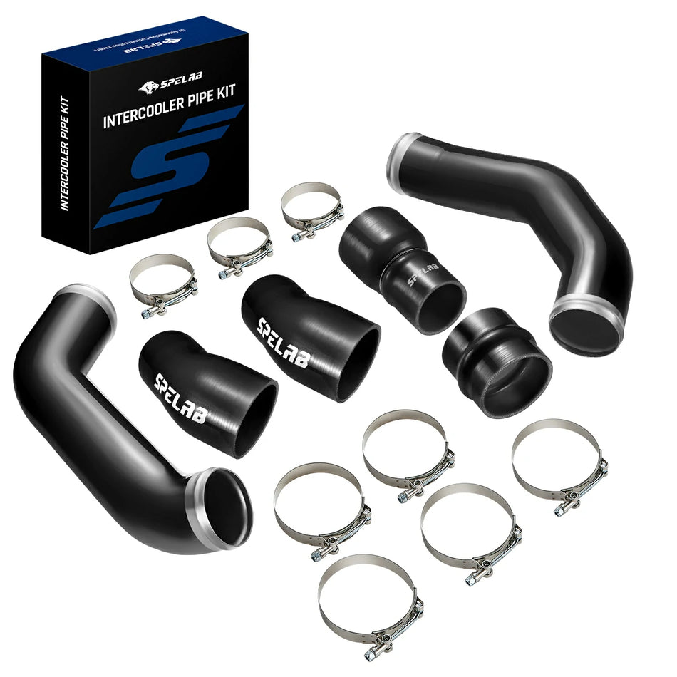
No boost immediately after a 6.7 Power Stroke intake manifold install usually points to a disconnected sensor, an unlocked electrical connector, a pinched seal, or a charge-air boot that was not fully seated during reassembly. Start with the parts you touched before blaming the turbocharger, fuel system, or new manifold.
Key Takeaways
A post-install no-boost condition should be treated as an installation-path diagnosis until scan data or a pressure test proves otherwise.
- Save all diagnostic trouble codes and freeze-frame data before clearing the PCM.
- Check the MAP sensor, intake airflow control valve, boost-pressure wiring, and connector locks first.
- Inspect every boot, O-ring, clamp, block-off plate, and sensor flange disturbed during the job.
- Start a regulated charge-air pressure test at about 5 psi and raise pressure only within the applicable service limit.
- Do not road-test under heavy throttle, Payload, or Towing load until actual boost follows commanded boost without a large leak.
The Five-Minute Post-Install Action Plan
Check the engine in the same order it was reassembled because a missed connector or crooked boot can often be found before any parts are removed again.

| Post-install symptom | Most likely inspection area | First action |
|---|---|---|
| No boost from the first start | MAP sensor, intake airflow control valve, boost sensor, or harness connector | Scan for circuit codes and physically pull-test each connector |
| Idles normally but falls flat under throttle | Cold-side CAC boot, throttle-body connection, clamp, or manifold seal | Inspect boot depth and clamp position, then pressure-test the charge-air tract |
| Loud hiss or rushing-air noise under load | Open charge-air joint, displaced O-ring, loose clamp, or uncapped port | Stop the load test and inspect for a directional oil-and-dust trail |
| P02E9 appears after the repair | Diesel intake airflow control valve circuit or connector | Check connector engagement, terminal position, reference voltage, and harness damage |
| P0299 returns only under load | Charge-air leak, sensor-data error, exhaust leak, or turbo-control problem | Compare commanded and actual boost before replacing another component |
| Black smoke with weak acceleration | Large boost leak downstream of the turbocharger | Inspect every boot and clamp that was loosened during installation |

- Save the full code list and freeze-frame data.
- Confirm the MAP sensor and intake airflow control valve connectors are fully locked.
- Verify that no harness is trapped under the manifold, bracket, or fuel-filter housing.
- Check every cold-side boot for full insertion, straight clamp placement, and visible damage.
- Inspect sensor O-rings, manifold seals, plugs, and unused ports.
Diagnose the Truck in Three Stages
A controlled three-stage inspection separates an electrical assembly mistake from a pressure-side leak without exposing the engine to a full-load test.
Before the First Start
The engine should remain off until every connector, seal, fastener, boot, and tool path has been checked against installation photos or the applicable service procedure.
- Verify that the MAP sensor is installed with an undamaged seal.
- Confirm that each electrical connector reaches its component without tension.
- Check that harness clips and brackets are not pulling a connector sideways.
- Confirm that rags, caps, tape, and temporary plugs have been removed.
- Verify that each manifold port contains the correct sensor, fitting, or plug.
At Idle
Idle data should be checked for believable sensor readings even though a large charge-air leak may not become obvious until the turbocharger builds pressure.
- Compare MAP and BARO with key-on, engine-off data before starting.
- Watch intake airflow position and sensor voltage for a fixed or implausible value.
- Listen for a sharp suction noise around the manifold and throttle-body area.
- Inspect for chafed wires, backed-out terminals, or a connector that has walked loose.
During a Light-Load Road Test
A short light-load road test is appropriate only after idle data looks credible and all visible charge-air connections pass inspection.
- Log commanded boost and actual boost rather than judging power by feel alone.
- Stop accelerating if a boot begins to hiss, whistle, swell, or move.
- Avoid trailer load, a steep grade, or a wide-open-throttle pull during the first test.
- Recheck clamp position after the engine cools if any joint moved under pressure.
Check the MAP Sensor Without Damaging the New Manifold
A loose MAP connector, damaged O-ring, contaminated sensor port, or stripped mounting hole can make a mechanically sound intake installation behave like a failed boost system.
Remove the sensor only after checking the connector and scan data. Inspect the O-ring for a flat edge, spiral cut, or pinched section. A dry O-ring can roll out of its groove as the sensor enters the bore, while excess sealant can block the pressure passage and corrupt the reading.
Clean soot or oily CCV residue with a sensor-safe method. Do not drive a pick, drill bit, or compressed-air nozzle into the sensing port. A blocked MAP passage can report a pressure value that changes slowly or stays close to BARO even as the engine begins making boost.
Match the sensor fastener to the instructions supplied with the cast-aluminum 6.7L Power Stroke intake manifold. Aluminum threads can be damaged when a small sensor bolt is cross-threaded, installed with the wrong hardware, or tightened as if it were a structural manifold fastener.
Do Not Trust a Connector Just Because It Looks Plugged In
A 6.7L Power Stroke connector can sit against its sensor housing without the terminals being fully engaged or the locking tab being secured.
Heat-aged connector bodies and locking tabs often become brittle on older or high-mileage trucks. The plastic can crack during removal, especially when the engine valley has seen years of Towing heat, oil film, dirt, and repeated service work. Friction alone may hold a damaged connector at idle, then vibration can pull it back far enough to open the circuit on the road.
Push each connector into place until its primary latch engages, close the secondary lock where equipped, and perform a light pull test. Inspect the MAP sensor, intake airflow control valve, boost-related sensors, and every connector moved to gain manifold access.
Check terminal depth from the face of the connector. A terminal that has backed out can touch intermittently while the connector shell still appears fully seated. Inspect loom sections near brackets and manifold edges for pinched insulation or stretched wires.
Ford’s service information specifically instructs owners to return electrical connector locking tabs to the locked position after air-induction service.[1]
Use the Trouble Code to Choose the Next Test
A diagnostic trouble code identifies the circuit or operating condition that failed its monitor; it does not automatically identify the part that must be replaced.
| Code or code family | What it points toward | Post-install checks |
|---|---|---|
| P0299 | Actual boost lower than the PCM expected | Boots, clamps, seals, charge-air piping, sensor plausibility, exhaust leaks, and turbo control |
| P02E9 | Diesel intake airflow position sensor circuit high | Disconnected connector, damaged lock, backed-out terminal, open circuit, short to voltage, or valve-related fault |
| P0236 | Boost-sensor range or performance problem | Sensor connector, pressure passage, wiring, and MAP/BARO/boost correlation |
| P0237 or P0238 | Boost-sensor circuit low or high | Reference voltage, signal circuit, ground, terminal fit, and damaged wiring |
| P0106, P0107, or P0108 | MAP circuit plausibility, low input, or high input | MAP connector, sensor seal, blocked port, harness tension, and terminal condition |
Ford identifies P02E9 as “Diesel Intake Air Flow Position Circuit High” in its 6.7L diesel OBD documentation.[2] Scanner descriptions can vary, so record the full code and the vehicle-specific description before clearing it.
A truck that retains only P0299 after all connector faults are repaired needs a broader P0299 underboost diagnosis rather than another round of blind part swapping.
Inspect Boots, Clamps, O-Rings, and Sealing Surfaces
A boot or O-ring can look installed while leaving a large enough opening to dump nearly all commanded boost under load.

Remove and reseat any connection that looks crooked. The tube should enter the boot evenly and reach the intended seating depth before the clamp is tightened. Position the clamp behind the retaining bead where the joint design requires it; a clamp sitting on the bead can force the boot outward as pressure rises.
Inspect the factory cold-side assembly for cracked plastic, separation near a crimped joint, and damage at the throttle-body connection. Ford TSB 19-2143 identifies CAC outlet tube disconnection at the throttle body or separation at the CAC tube crimp clamp as causes of lack of power with P0299 on certain 2011–2016 6.7L trucks.[3]
A 6.7L Power Stroke cold-side intercooler pipe kit can remove the original plastic or crimped-tube failure mode when its listed fitment matches the truck, but its boots, clamps, sensor provisions, and O-rings still require correct installation.
Use the system layout and failure location to decide which side of the charge-air system should be replaced first.
Pressure-Test the Charge-Air System Safely
A regulated static pressure test can expose a post-install leak quickly, but the test pressure must stay within the vehicle procedure and the rating of the lowest-rated plug, boot, intercooler, sensor seal, or adapter in the test setup.

- Secure the tester and every blocking plug with hardware intended for charge-air testing.
- Start at about 5 psi to find a disconnected pipe, uncapped port, or badly displaced seal.
- Apply soapy solution around boots, MAP flanges, plugs, manifold joints, and CAC end tanks.
- Increase pressure gradually only when the low-pressure inspection finds no leak.
- Stop at the service-procedure limit or the lowest-rated component limit, whichever is lower.
- Never connect unregulated shop air directly to the intake tract.
A universal 30–35 psi ceiling is not safe advice for every truck or homemade tester. Cap design, model year, intercooler condition, boot construction, and test location all change the safe limit. A leak large enough to cause immediate no boost after installation will often reveal itself before maximum operating pressure is reached.
Keep hands and your face out of the path of plugs and boots during the test. Stored air can launch an inadequately retained cap with enough force to cause serious injury.
Separate an Installation Error From a Defective Part
A repeatable leak from the manifold casting or a correctly assembled sealing surface suggests a component problem, while a leak from a disturbed boot, pinched O-ring, open port, or connector points to installation.
| Finding | Most likely category | Best next action |
|---|---|---|
| Connector not latched or terminal backed out | Installation or harness damage | Repair the lock or terminal and verify live data |
| O-ring cut, rolled, or pinched | Installation or seal mismatch | Replace the seal and inspect the bore for burrs |
| Boot not seated past the intended joint position | Installation | Clean, reseat, align, and tighten to the supplied specification |
| Leak through a visible casting defect | Component defect | Document the leak location and contact the manufacturer |
| MAP bolt hole damaged during tightening | Installation damage or hardware mismatch | Stop tightening and assess thread repair or replacement |
| No external leak and sensor data is plausible | Problem may be outside the installation area | Continue with exhaust, VGT, fuel, and turbo-control diagnosis |
Photograph the installation, leak-test bubbles, seals, ports, and hardware before disassembly if a product claim may be needed. Evidence collected before a second teardown is much more useful than a general statement that the truck would not build boost.
Does the PCM Need a Reset After the Install?
A stock-replacement intake manifold installation normally does not require a PCM reset to restore boost, and a reset will not repair an unplugged sensor, leaking boot, pinched O-ring, or open pressure port.
Clear codes only after saving freeze-frame data and correcting the fault. Some learned values may readapt during normal driving, but a truck with immediate no boost or an active circuit code should be diagnosed before any adaptive reset is treated as the repair.
A calibration change may be required when a modification changes airflow-control hardware, sensor scaling, or emissions-system configuration. Follow the product instructions and applicable emissions rules rather than assuming every Bolt-on manifold needs tuning.
Choose the Repair That Matches the Confirmed Failure
The correct repair replaces or corrects the part that failed the inspection, live-data check, or pressure test rather than the part most closely associated with the fault-code wording.
- Repair a damaged connector lock or terminal when vibration causes the sensor signal to drop out.
- Replace a pinched seal when bubbles form around a sensor boss or manifold port.
- Reseat the boot when the tube is shallow, crooked, or the clamp is positioned incorrectly.
- Replace a split or separated factory CAC pipe when the pipe itself cannot hold test pressure.
- Document and replace the manifold only when the casting, flange, threaded boss, or supplied component is confirmed defective.
An intake manifold and intercooler pipe bundle makes sense when inspection confirms problems in both assemblies or when planned preventive replacement matches the truck’s exact year and configuration. Compare the listed fitment and durability checkpoints before ordering.
Different trucks and build years can use different sensor provisions, pipes, and connection details, so verify the vehicle against the complete Power Stroke intake manifold lineup before treating physical resemblance as fitment confirmation.
Frequently Asked Questions
These answers cover the installation-specific questions that remain after the initial connector, seal, scan-data, and pressure checks.
What should I do if I stripped the MAP sensor bolt hole in a cast-aluminum manifold?
Stop tightening the bolt and remove the sensor so the thread damage can be inspected. Minor thread damage may be repairable with the correct insert and adequate surrounding material, but drilling or tapping with the manifold installed can send metal chips into the intake. Replace the manifold when a safe thread repair cannot preserve sensor alignment, sealing, and wall thickness.
What causes P02E9 after a 6.7 Power Stroke intake manifold install?
P02E9 after intake work commonly directs the diagnosis toward the diesel intake airflow position circuit, including an unlocked connector, backed-out terminal, damaged wire, missing reference voltage, poor ground, or a fault in the airflow-control assembly. The code does not prove that the new intake manifold is defective.
Why does my 6.7 Power Stroke hiss only when it builds boost?
A hiss that appears only under boost usually indicates pressurized air escaping from a boot, clamp, O-ring, manifold joint, CAC pipe, or intercooler. A static regulated pressure test is the safest way to locate the leak without repeating a hard road pull.
Can an incorrectly installed boot cause black smoke?
A large post-turbo air leak can cause weak acceleration and black smoke because the cylinders receive less air than the operating condition demands. Stop heavy-throttle testing until the boot is seated correctly and actual boost follows commanded boost.
Should I use sealant on the MAP sensor O-ring?
Use only the lubricant or sealing method specified by the sensor, manifold, or vehicle procedure. Excess sealant can contaminate the MAP sensor, block its pressure passage, or allow the O-ring to move out of position during installation.
When should I return or replace a newly installed intake manifold?
Return or replace the manifold when a controlled inspection confirms a casting leak, incorrectly machined sealing surface, unusable threaded boss, wrong fitment, or missing supplied component. A disconnected sensor, damaged vehicle harness, displaced seal, or loose external boot should be corrected before the manifold is blamed.
Sources
Official Ford and U.S. government-hosted service documents support the connector, code-definition, and CAC failure references used in this guide.